Net Labels, Ports & Ground
Ground
Place a ground symbol (, then ground) on
any node that is the circuit reference. Its net is always 0 — the SLiCAP /
SPICE reference node.
Net labels
A net label gives a wire a readable name (in, out, vdd …) that
is used in the netlist and shown on the drawing.
Choose (shortcut L) and click the wire, or double-click a wire segment to open its net-label dialog.
Type the name and choose whether to display it.
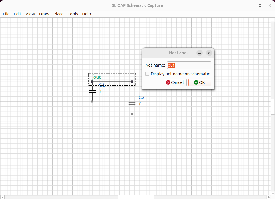
Fig. 35 A net label naming the output node out.
All wires that are electrically the same net share one name.
Ports
A port symbol marks a named connection point. Two ports with the same name are connected even when no wire runs between them, which keeps busy drawings readable and is the basis for hierarchical connections.
Parameter definitions
Use to add a parameter table to the
schematic — a list of name = value definitions (for example
R_s = 825, C_L = 10e-12). These become .param lines in the netlist
and are typeset as a neat table on the figure.
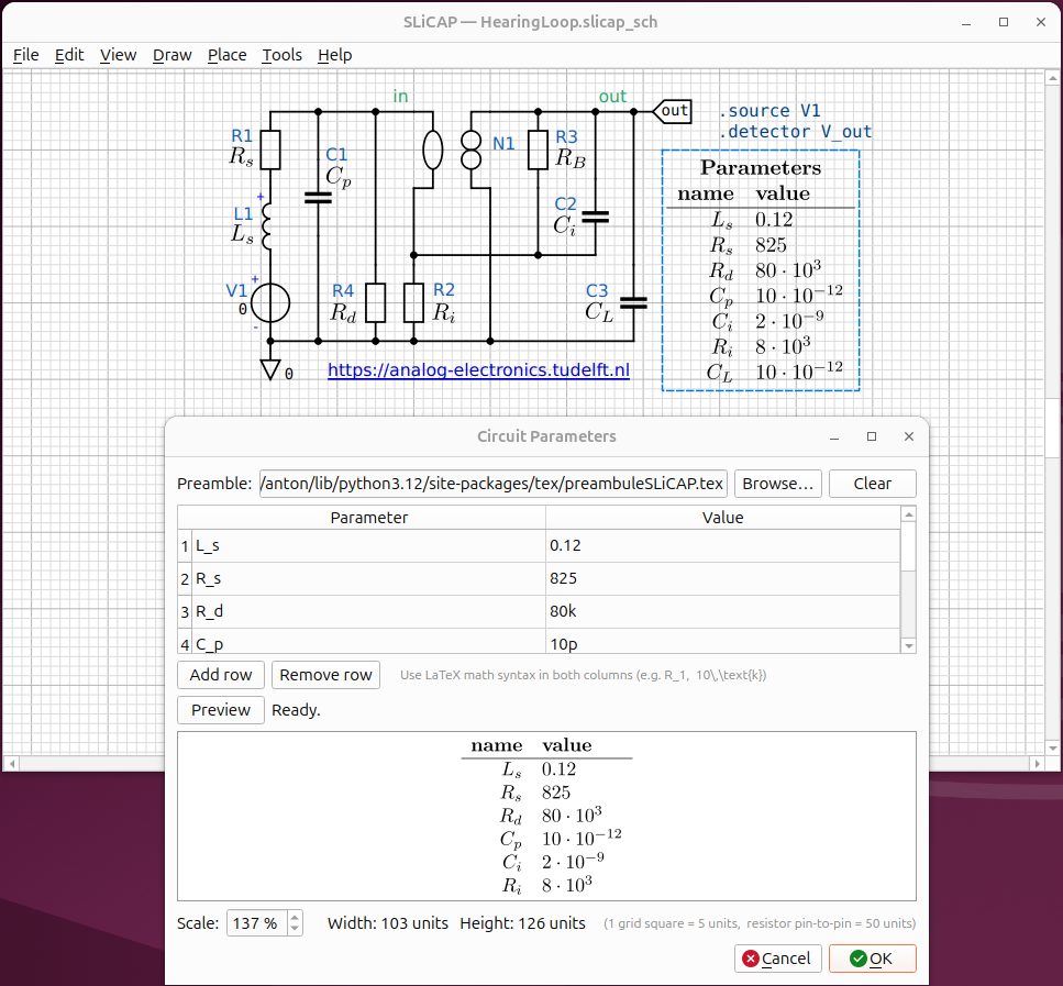
Fig. 36 A parameter table rendered on the schematic.
Designating source, detector and loop-gain reference
For a SLiCAP analysis you must say what is driving the circuit and where you observe it:
Choose .
Set the source (an independent source, e.g.
V1), the detector (a node voltage or branch current, e.g.V_out) and, optionally, the loop-gain reference.
These are written as the corresponding SLiCAP commands in the netlist.