Component Properties
Double-click a placed component (or select it and open its context action) to edit its properties.
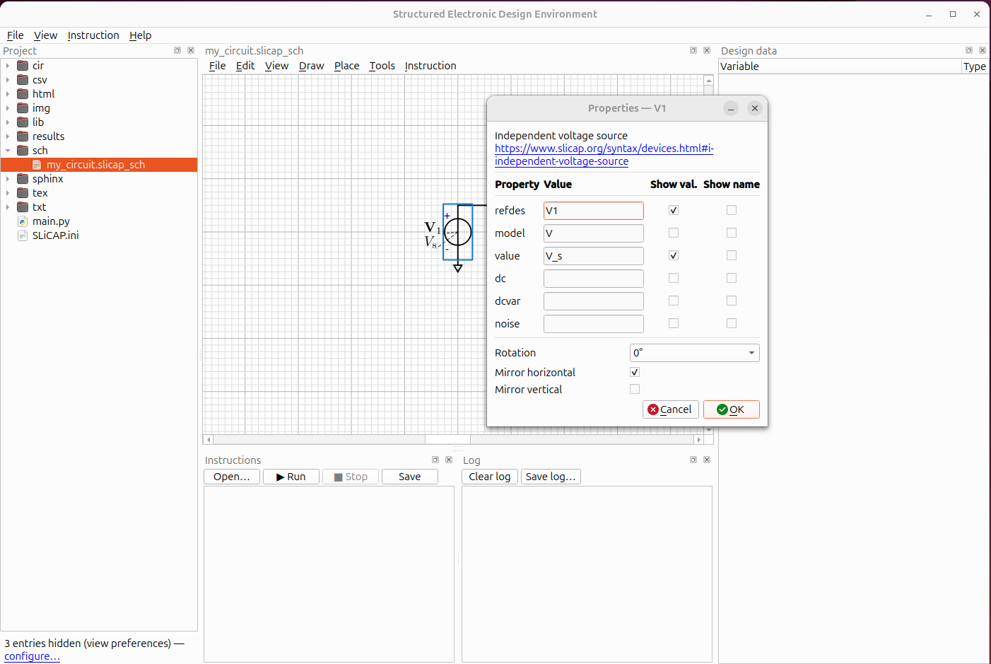
Description and documentation link
At the top of the dialog the symbol’s description is shown in bold, and —
when the symbol provides one — a documentation link. The link is taken
from the symbol’s data-info metadata and opens in your web browser; it can
point to a help page, a datasheet or a model definition.
Reference designator
The refdes is the element’s unique name on the schematic (R1, C3,
N1 …). It becomes the element name in the netlist.
Model
Each SLiCAP symbol carries a SLiCAP model name. It is shown for reference and is written into the netlist.
Parameters
The parameter rows are the values you can set for the element — for example a
resistor’s value, or a source’s dc and noise. The available
parameters come from the symbol itself.
Enter a number (
1k,2.2e-9) or a symbolic expression. Symbolic expressions do not need to be placed between curly brackets{}
Value notation (scale factors)
All values entered in the GUI — component values, parameters, and the fields of the instruction dialogs — use SLiCAP notation. Scale factors are case-sensitive:
|
|
|
|
|
|
|
|
|
|
|
|
|
NGspice schematics
NGspice itself reads scale factors case-insensitively (m and
M are milli, whereas mega is Meg).
You ALWAYS enter SLiCAP notation —
SLiCAP translates automatically wherever values are written into NGspice
input (netlists, .param lines, instruction arguments): all suffixes
are expanded numerically.
References
Some elements reference another element — for example a current-controlled
source (H/F) names the voltage source whose current it senses, and a
coupling factor K names the two inductors it couples. These appear as
ref rows.
Showing and hiding labels
For each property there are two check-boxes:
Show value — draw a label for this property on the canvas.
Show name — prefix the value with its name (
value: 1kinstead of1k). Only available when Show value is on.
Labels you switch on can be dragged to any position around the symbol; a thin dashed leader line connects a label to its component while it is selected.
Orientation
The lower part of the dialog sets:
Rotation — 0°, 90°, 180° or 270°.
Mirror horizontal / vertical — flip the symbol.
Labels stay upright and readable regardless of the symbol’s orientation: a symbol rotated by 0 or 180 degrees shows them upright, one rotated by 90 or 270 degrees turns them to read bottom-to-top, and a mirrored symbol never mirrors them.
Change symbol
Change symbol… gives the component another symbol of the schematic’s
library, for instance one drawn in the symbol editor. Offered are the
symbols with the same number of pins and, for a built-in element type, the
same prefix; the wires on the pins follow the pins to their new places.
For a subcircuit block any symbol with the right number of pins is
offered, with the subcircuit’s ports assigned to the symbol’s pins in a
list (Up and Down move a port to another pin) and a preview. The
result is written into the project’s lib folder as the block’s symbol,
as does, so the netlist order of the
ports is unchanged and other schematics of the project pick it up with
.
DC operating-point annotation (NGspice)
On NGspice schematics, independent voltage sources and inductors offer a
Show DC operating current check-box in their Properties dialog, and the
Net Label dialog (double-click a wire) offers Show DC operating voltage.
Checking them places an I: <value> / V: <value> text on the canvas.
The values come from the circuit’s most recent unstepped operating-point
run (sl.op(...) in the instruction file, which writes
cir/<circuit>_op.raw). They are updated after every run, shown greyed
and italic while no results are available (V: —) or after the schematic
was edited (stale). They are never stored in the schematic file — only
the check-box and the label position are.
Currents follow the NGspice sign convention: I(V...) and I(L...)
are measured into the positive terminal, so a source that delivers
current to the circuit reads negative. A 0 V voltage source in series
with a branch therefore acts as a branch current detector.
Colour, font, and the number of digits are set in the schematic
preferences under Bias annotation (engineering notation with SLiCAP
scale factors, e.g. 1.23m).